FAQ
Home > Products > Transformer Foils > Copper Foils for Transformer Windings
copper foils
copper foils

Copper Foils for Transformer Windings

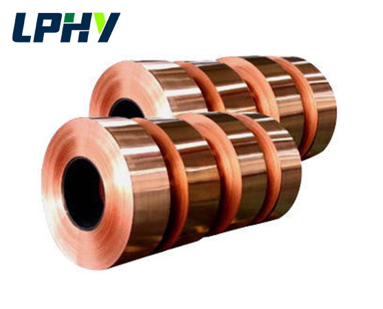
Copper Foils are thin, flat sheets of copper used as conductors in transformer windings, especially in foil-wound transformers. They are an alternative to traditional round or rectangular enameled wire for certain applications.
Grade Cu-ETP/C-11000/E -Cu58
Temper Soft(O),Hard(H)
Dimension Thickness: 0.1-4.0mm; width: 20-1500mm
Share:
Product Briefing
Relevant Parameters
Advantages of the Copper Foil
PDF Download
Product Briefing

Copper foils are a type of ultra-thin, wide-width, high-purity copper strip material specifically designed for use as conductors in the coil windings of foil-wound transformers. They are also a highly competitive alternative conductive material for the core winding designs of medium- and low-voltage high-current transformers, dry-type distribution transformers, energy storage and power conversion equipment, and medium-frequency power supply transformers, and represent a highly competitive alternative to traditional round enameled wire and rectangular enameled flat wire.

In traditional transformer winding design systems, the industry has long relied on single or multiple parallel enameled round wires or flat copper wires to carry winding currents. These wires are wound into coils by stacking round or rectangular cross-sections, which—under high-current conditions—are highly prone to inherent defects such as the skin effect, proximity effect, low winding slot fill factor, excessive leakage inductance, and narrow heat dissipation channels. In contrast, copper foil windings use a single continuous strip of thin copper foil as the conductor for each turn, with each turn completely covering the effective width of the core window. This fundamentally redefines the logic of electrical conductivity, heat dissipation, and magnetic coupling at the structural level, offering irreplaceable performance advantages under high-current, low-voltage conditions. Currently, this technology has been widely adopted in dry-type distribution transformers, isolation transformers for photovoltaic energy storage inverters, medium-frequency induction heating power supplies, rail transit auxiliary converters, and high-power UPS systems.

In terms of product application boundaries, copper foil windings cannot completely replace all enameled wire windings but are clearly distinguished by specific application scenarios: in low-voltage, high-current windings; multi-turn compact coils; models with strict lower limits on leakage inductance parameters; and equipment with limited heat dissipation space, the comprehensive performance of copper foil fully surpasses that of traditional enameled wire; However, in high-voltage, multi-turn, low-current winding applications, solutions such as enameled round wire and transposed wire will still be the preferred choice. The two technologies complement each other, allowing engineers to flexibly select and combine them based on the equipment’s voltage rating, rated current, size constraints, and temperature rise specifications.


Transformer copper foils uses the best electrolytic copper or special copper alloy as raw materials. Fully protect the electrical conductivity of the transformer copper foils, conductivity 97-102% IACS(international annealed copper standard value) used in the power industry high and low voltage transformer line dry type transformer, shallow sea, deep sea, long-distance multi-channel and microwave system communication cable. The narrow and thin belt with large roll diameter (the length can reach more than 2000 meters) and the width is greater than 600mm. It is similarly as application of enemeled copper wire.


The requirements of transformer copper strips are as follows:
1. Strip shape should be flat and true, allowing slight waves, strip side bending degree should not be greater than 2mm/m
2. Strip edge: cut edge, rounded edge, round edge
1) The cutting edge should be cut neatly, split edge and rolled edge, thickness ≥0.4mm, edge burr < 0.05mm; Thickness < 0.4mm; Edge burr < 0.03mm
2) Rounded corners, the edge should not be sharp, rough or protruding edge

Relevant Parameters

Copper Foils For Transformer Winding Technical parameters


Name Copper Foils
Grade Cu-ETP/C-11000/E -Cu58
Temper Soft(O),Hard(H)
Dimension Thickness: 0.1-4.0mm; width: 20-1500mm
Standard ASTM,EN 13599,GB-T 18813-2002
Packing: In coil, Inner Diameter: 300mm, 400mm, 500mm, etc. IEC, NEMA, GB, JIS


The standard of Copper Coils


INDUSTRY USA ITALY CHINA EURONORM JAPANESE
STANDARD ASTM B5, B152 UNI 5649 GB/T EN 1652 DIN 1976 JIS
C1100 C11000 Cu-ETP T2 CW004A E-Cu 58 C1100
Advantages of the Copper Foil

Extremely Large Heat Dissipation Surface Area

The copper strips consists of a single, flat, thin sheet, with both sides of the single-layer conductor in direct contact with the cooling medium (air convection in dry-type equipment or circulating insulating oil in oil-immersed equipment). The effective heat dissipation surface area is significantly larger than that of stacked windings made of round or flat wires with the same conductive cross-sectional area.

In traditional coils made of multiple stacked enameled wires, the wires obstruct each other, causing a large portion of the heat dissipation surface to be enclosed by adjacent wires. Heat accumulates inside the coil and struggles to dissipate outward, making it highly prone to the formation of localized high-temperature hot spots; In contrast, each layer of copper foil in a foil-wound winding has a fully exposed heat-transfer surface, and the insulating paper or film interleaved between layers forms uniform heat-dissipation channels. The cooling medium can flow evenly across the surface of every layer of copper foil, resulting in a short heat transfer path and high heat exchange efficiency. Under the same rated current conditions, the average temperature rise of foil-wound transformer windings is 10–20°C lower than that of enameled wire windings. This significantly mitigates the aging and damage to insulation materials caused by high temperatures, extending the service life of the entire transformer. It is particularly suitable for large-power industrial equipment operating continuously at full load 24 hours a day.

Higher Winding Fill Factor

The fill factor (slot fill rate) and leakage inductance are the two core electromagnetic parameters of transformer windings, and the copper foil structure offers dual advantages in both areas.

First, high fill factor: Custom-made wide, thin copper strip eliminates the curved gaps found in round wire windings, allowing the entire sheet of conductor to fill the winding slots. This increases the proportion of effective conductive metal by 10%–18%. For the same core slot dimensions, copper foil windings can carry a higher rated current, enabling smaller, lighter transformer designs that reduce the unit’s footprint and weight;

Second, extremely low leakage inductance: In traditional windings using multiple parallel enameled wires, the spatial distribution of the wires is dispersed, resulting in diffuse magnetic field coupling between the windings and the core, as well as between the primary and secondary windings. This leads to high leakage flux and elevated leakage inductance values; In contrast, a single turn of copper foil completely covers the width of the core, resulting in highly concentrated magnetic field coupling between the primary and secondary windings. Leakage flux is significantly suppressed, and winding leakage inductance can be reduced by 30% to 60%. The advantage of low leakage inductance is critical for medium-frequency power supplies, photovoltaic inverters, and high-frequency UPS equipment, as it reduces reactive power losses in the circuit, suppresses output voltage spikes, minimizes stress on switching devices, and enhances the operational stability of power conversion systems.

Perfectly Suited for High Currents

Low-voltage-side windings represent the most common application scenario for copper foil, such as the low-voltage windings of 10 kV/0.4 kV distribution transformers, the low-voltage coils of isolation transformers in energy storage converters, and the secondary windings of high-power rectifier transformers. These operating conditions are generally characterized by low voltage and extremely high output current.

If multiple strands of enameled flat wire are used in parallel to carry high currents, uneven current distribution between the strands is highly likely, causing some strands to overheat due to overload. Furthermore, as the number of parallel-wound strands increases, the complexity of wire arrangement and repositioning processes rises exponentially; In contrast, a single sheet of copper foil acts as a single-turn conductor, with current distributed uniformly across the entire width of the copper sheet. This eliminates the issue of uneven current distribution among parallel conductors. A single turn can carry several thousand amperes of steady-state current, resulting in a simpler winding structure and streamlined winding process. There is no need for complex phase-shifting designs, significantly improving mass production efficiency. For short-term short-circuit surges involving high currents, the integrated conductive structure of the single-piece copper foil also offers greater resistance to current surges than a configuration with multiple discrete conductors.

Effectively Reduces Skin Effect Losses Under Specific Operating Conditions

The skin effect is the primary source of loss caused by uneven current distribution within a conductor under an alternating magnetic field: alternating current concentrates on the outer surface of the conductor, with virtually no current flowing through the central region, resulting in a reduction of the effective conductive cross-sectional area and a significant increase in AC losses.

The copper foil is designed as an ultra-thin sheet, with a conductor thickness far below the skin effect penetration depth at power and intermediate frequencies. As a result, current is uniformly distributed throughout the entire thickness of the copper foil, preventing the phenomenon of current concentration at the surface and underutilization in the interior. Compared to thick round copper wire or thick flat copper wire with the same conductive cross-sectional area, thin copper foil windings can reduce additional AC losses by 25% to 50% in the 50 Hz to 10 kHz frequency range. The structure of the conductor cross-section naturally suppresses high-frequency and power-frequency skin effect losses, further optimizing the overall energy efficiency of the transformer and aligning with the industry’s demand for energy conservation and carbon reduction in power equipment.

High Mechanical Strength of the Coil

Copper foil windings also offer additional practical engineering value: the continuous copper foil formed into a coil structure provides excellent structural integrity. After interlayer insulation with varnish-impregnated paper and curing, there is no risk of loosening or displacement. Under the instantaneous electrodynamic forces generated by a short-circuit fault, the winding is less prone to deformation or misalignment of the wire arrangement, resulting in superior short-circuit withstand capability compared to windings made of multiple discrete enameled wires. At the same time, standardized foil winding machines can fully automate copper foil feeding, synchronized insulation insertion, continuous winding, and terminal lead processing. This high-yield automated mass production is well-suited for the standardized production of high-volume dry-type transformers, and long-term batch manufacturing can effectively control the processing cost per winding.

High Voltage Applications
High Electrical Conductivity
Reduced Electromagnetic Interference
Low Resistivity
Enhanced Dielectric Strength
Corrosion Resistance
Areas of application
Your Satisfaction ls Our Successe

    Quick Question And Answer
    30+ Years Experiences Shipping Team To Ensure The Competitive & Best Shipping Solution